Photometric Solid Guide: Curves, Diagrams, and Digital Files

To accurately predict how light will behave in space and on architectural surfaces,it is not enough to know the lumens emitted by a luminaire.It is necessary to precisely map its directional distribution.
This geometric and energetic survey generates the
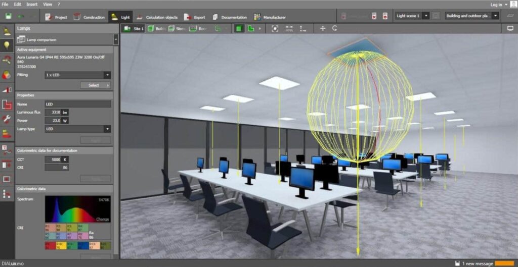
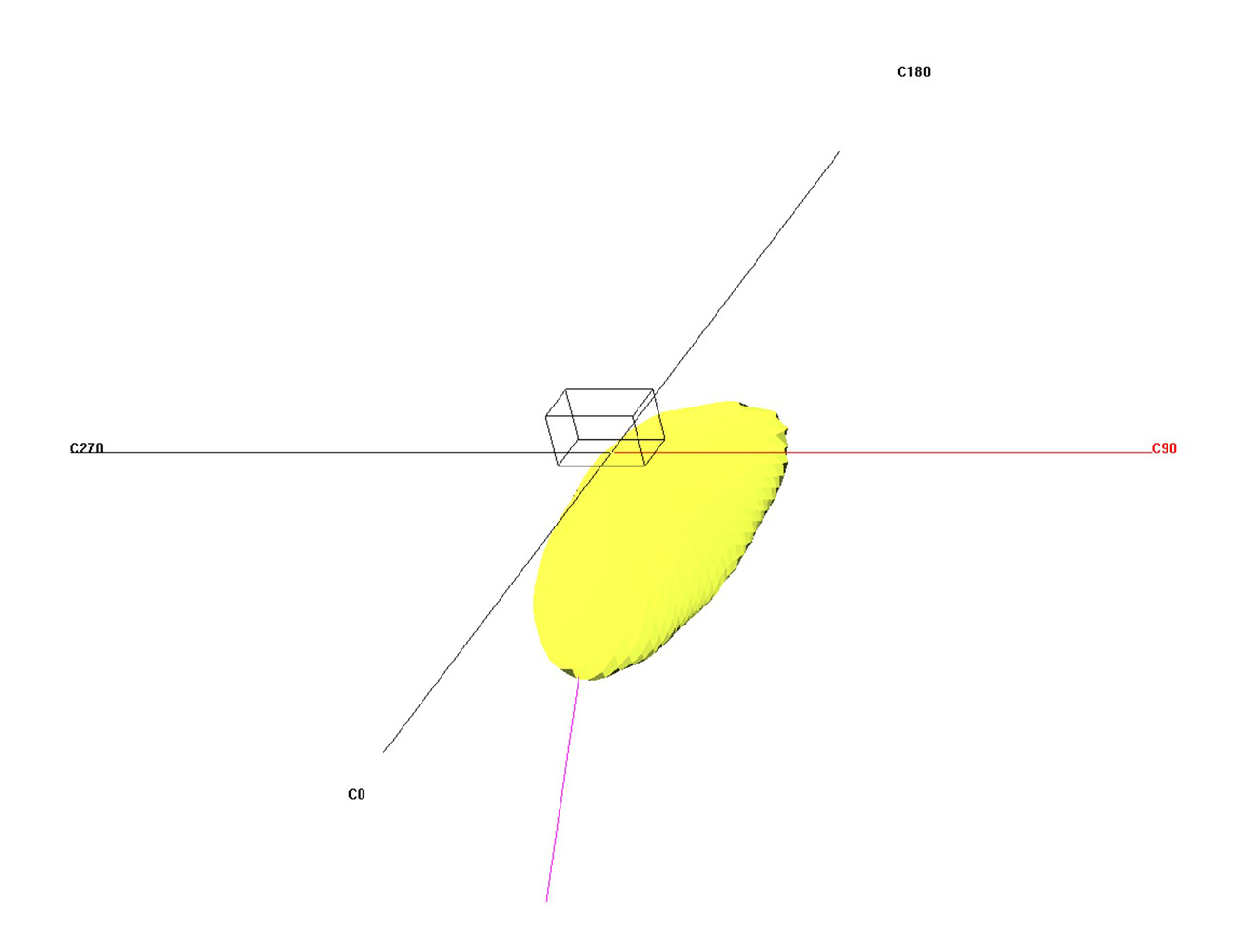
Photometric Solid, the fundamental tool that allows planners and lighting designers to simulate lighting in virtual environments (using software such as Dialux or Relux).
What is the Photometric Solid?

The photometric solid is the three-dimensional representation of the luminous intensity (measured in candelas) emitted by a light source in all directions in space.

It is generated in the laboratory using an instrument called a goniophotometer, which rotates the turned-on device (or a sensor around it) and measures the candela value for each solid angle.The three-dimensional envelope obtained by combining all the intensity vectors is the photometric solid. Its shape determines the visual “imprint” that the light will leave on the architecture.

From 3D to 2D: The Polar Diagram (Photometric Curve)

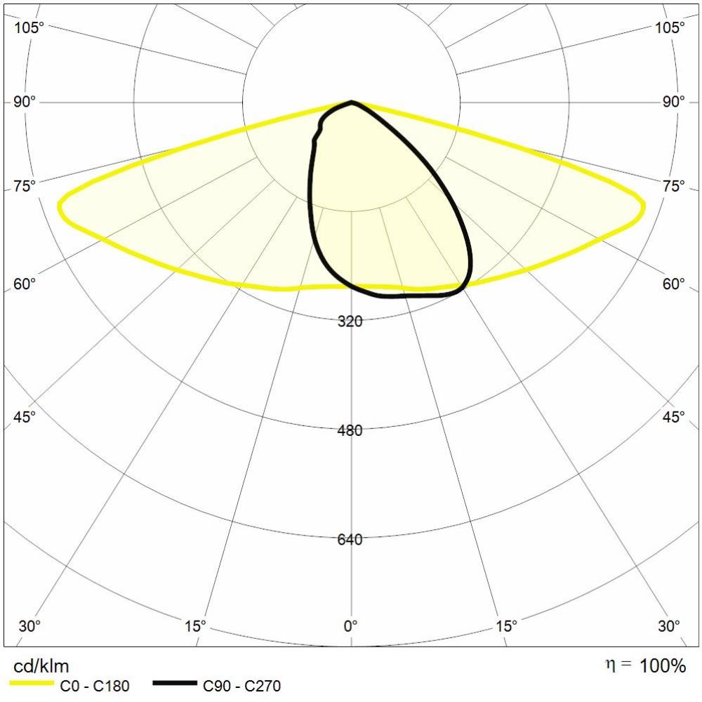
Because a 3D volume is complex to interpret on a paper datasheet or monitor, the solid is “sliced” along vertical and horizontal planes. The resulting two-dimensional cross-section is the Photometric Curve, usually represented in a polar diagram.

The most widely used international reference system for technical lighting is the C-Gamma system (C-γ):

  • The C (0°-360°) planes rotate around the vertical axis of the fixture.

  • The Gamma (γ 0°-180°) angles indicate the inclination of the beam from the vertical (where 0° is the light pointed straight down – Nadir).

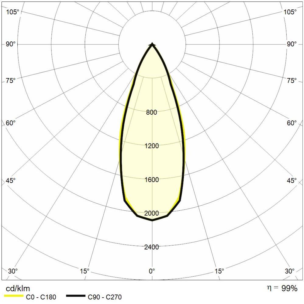
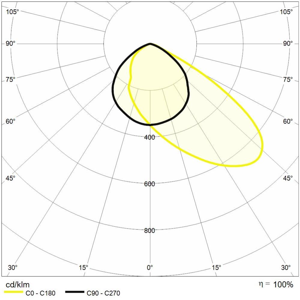
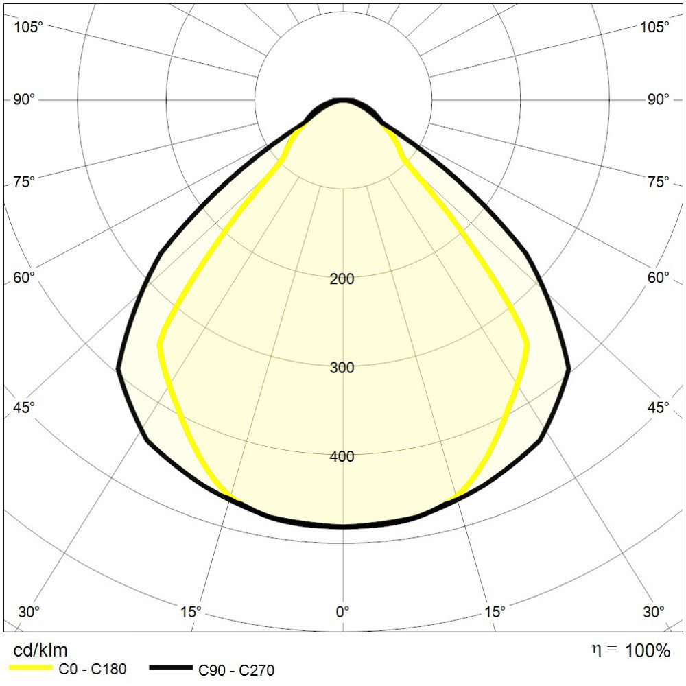
In datasheets, the photometric curve typically shows two main planes:

  1. Plane C0 – C180 (yellow line on the ReeR website): Cross-section or longitudinal axis of the luminaire.

  2. Plane C90 – C270 (black line on the ReeR website): Section orthogonal to the previous one.

If the device has a perfectly circular optics, the two lines will overlap into one.

Types of Optical Distribution

The shape of the solid defines the optical classification of the luminaire, a vital parameter in choosing the right product for each outdoor or indoor application.

Rotosymmetric

Asymmetric

Elliptical

Street (“Batwing”)

Optics Type Solid Shape Typical Lighting Application
Rotosymmetric
(Spot / Flood)
A cone or “balloon” perfectly symmetrical about the vertical axis (C0 = C90). Recessed spotlights, downlights, accents on columns, lighting tall and narrow facades.
Asymmetrical The solid is unbalanced forward, “cutting” the light backwards. Wall-mounted spotlights for facades (wallwashers), courtyard lighting, signage, where it is necessary to avoid light dispersion behind the device.
Elliptical Narrow on one axis (e.g., 10°) and wide on the other axis (e.g., 45°), forming an oval blade. Grazing on textured walls, cornice lighting, enhancing linear architectural elements.
Batwing A complex “batwing” shape, very wide transversely and narrow from the front. Street lighting, pedestrian walkways, large parking lots (optimizes the spacing between poles, reducing glare).

Digital Formats: LDT and IES Files

To be calculated by design software, the entire database of angular coordinates and intensity of the photometric solid is compressed into standardized text files. The two universal formats are:

  • EULUMDAT (.ldt): This is the European reference standard. It contains not only the candela matrix, but also the physical data of the device (dimensions of the emitting surface), the electrical power (W), and the nominal and actual luminous flux.

  • IESNA (.ies): This is the North American standard. Similar in concept, it differs slightly in its computer structure and the management of multiplication factors.

Absolute Photometry and LED Technology: In traditional discharge lamps, photometric files were “relative” (calculated on a theoretical flux of 1,000 lumens) because the same optic could accommodate bulbs of different wattages. Today, with LED architecture, the optic and the source form an integrated, inseparable system.
Our fixture measurements use Absolute Photometry: the lumens and candelas described in the LDT file correspond exactly to the actual performance of that specific fixture, eliminating any margin of error in lighting design calculations.

Summary: The Heart of Lighting Design

The photometric solid is the bridge between product engineering and the art of architectural design.Relying on photometric files (.ldt) that are accurate, up-to-date, and measured with minimal tolerances is the only way to ensure that the calculated lux Virtually in the design phase, they correspond exactly to the span measured on site once installation is complete, complying with regulatory constraints (CEI EN 12464) and enhancing the architecture.